Configuration Guide MR600 v1/v2/v3/v5 4G/+ External Antenna Information (LPDA MIMO) Australia - John VK3HJQ
MR600 v1/v2/v3/v5 4G/+
External Antenna Information
LPDA(Log-periodic dipole array)
MIMO(Multiple Input - Multiple Output)
Australia (AU) - John vk3hjq
Important information: (MR600 V2 FW 1.6.xxx)
https://community.tp-link.com/en/home/forum/topic/615176
(VK3HJQ Licensed Amateur (HAM) Radio Operator in Australia)

Please check the specifications for use in other countries other then Australia, the information here relates to the Archer MR600 versions 1, 2, 3 & 5 plus any other models that are fitted with two Detachable 4G LTE Antennas, the Information is/was current at time of posting in August 2021 (E&EO)
TIPS :
1. Be very wary of some antennas claiming incorrect & or inflated gain (dBi) figures.
2. Keep coax cable runs as short as possible to reduce signal loss.
3. Use good quality LOW LOSS coax like LMR400, do not use the thin type coax which have massive losses.
4. Use a phone app to find the closest Mobile/Cell tower for correct antenna alignment.
5. Be wary of over head power lines when erecting antennas.
6. Keep antennas away from metal structures & clear of trees for line of sight to the cell tower/s
7. A must is correct earthing, to reduce Static & protect against lightning.
Archer MR600 AU https://www.tp-link.com/au/home-networking/3g-4g-router/archer-mr600/


A Quick Summary here.....
Mobile Van Setup Video
https://www.youtube.com/watch?v=Vd2r-8Dm4oY


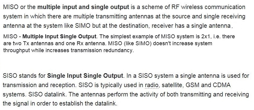
Note: The MR600 will auto switch from (4G+) 2X2 MIMO (2 Antennas - AUX & Main) to (4G) MISO/SISO (1 Antenna - Main) if the signal strength is to low.
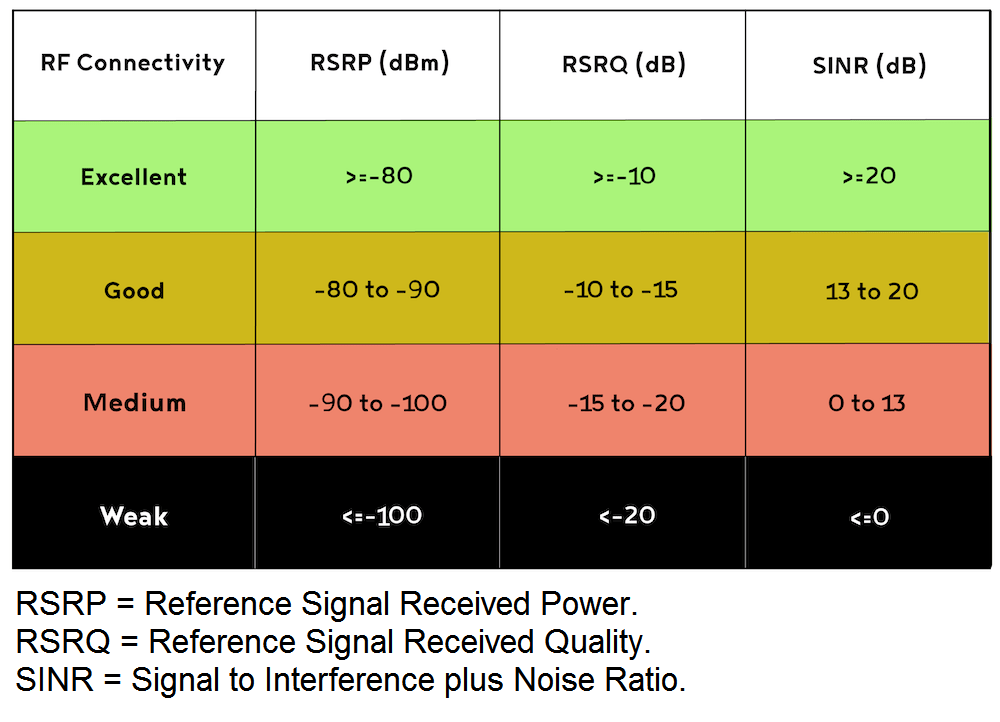
RF Connectivity


Portable speed & range tests
Queensland Australia
(A little Queensland Australia test drive - Wow 13,000km [8077 miles])
TP-Link Archer MR600 V2 (Cat 6) 12Volt Solar powered.
Maximum speed achieved with 2 x LPDA (10-11dBi) Antennas was 140Mbps/40Mbps (2X2 MIMO 4G+) @ *8km's from the cell tower, compared to 1 x magnetic mount 7dBi antenna on the roof @ 40Mbps/20Mbps (MISO/SISO).


Test @ a No Signal location
**10.8km from the closer cell tower with Mountains in between, in a NO Signal area according to the phone app, but the Signal still got through, even though is was a bit slow. (13.0Mbps/1.47Mbps @ 52ms MISO/SISO).

https://static-community.tp-link.com/attach/27/9/2021/2c0c0cdd24574b81b3875f898689507a.mp4
Full Video here.....(1:03) https://youtu.be/Vd2r-8Dm4oY
Antennas laying down on the roof, not far from the cell tower/s, great reception (4G+ 2X2 MIMO Full Signal).


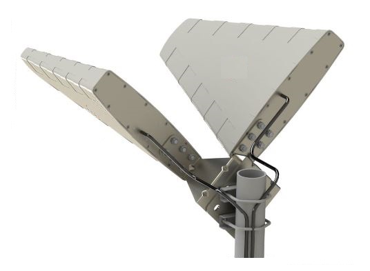
Higher gain in dBi, equates to longer length of the LPDA Antenna.
**************************************************
Technical info


NOTE: The LPDA Antenna is feed from the front, meaning the coax is connected to the front of the Antenna & not the back.

https://community.tp-link.com/en/home/forum/topic/614762


Cat 4 - MISO/SISO Connection
1 external LPDA Antenna
Never EVER use these types of 2 way splitters ('Y' patch lead) to connect 1 Antenna to the 2 Antennas ports (Main / Aux).


Always have 2 Antennas connected, it will NOT work with ONLY the AUX Antenna connected, (unless a very high signal is present) but it will work with the Main Antenna connected.
NOTE: (Never leave the Antenna input open circuit with no 50ohm load connected, meaning always have both Antennas connected even if ONLY using 1 external LPDA Antenna)


1 Antenna (LPDA) Main (-45 Deg/135 Deg) connected to the Main Antenna Input for MISO/SISO operation. (MUST have internal Antenna still connected to AUX)
Cat 6 - 2X2 MIMO Connection
2 external LPDA Antennas
2 Antennas (LPDA) Main & AUX, AUX @ 45 Deg & Main @ 135 Deg (-45 Deg) then connect to the (Main & AUX) Antenna inputs respectively.

Why you MUST mount the 2 LPDA Antennas on a Slant Angle & Not Vertical or Horizontal for 2X2 MIMO operation

Good, Better & Best/Optimum way to mount LPDA Antennas


You can mount the LPDA MIMO Antennas vertically on either the Right or Left (Left preferred) side of the mast/pole, always make sure the arrow/s on the LPDA Antenna/s is pointing up.  & the Antennas should be mounted a minimum of 42.8cm (1 wavelength @ 700MHz) apart & for Optimum performance, mount them 85.6cm (2 wavelengths @ 700MHz) apart.
You can also mount them the other way around if you require a better Main signal, (because of the Antenna spacing required) but this could drop your 2X2 MIMO signal out too & go back to 1X1 MISO/SISO operation, this means now having the Main @ the Top & AUX @ the Bottom/Underneath.
For the BEST performance, a better solution would be to mount them horizontally instead to allow for the Optimum spacing required @ 700MHz (lowest frequency used) of 85.6cm apart. (both LPDA Antennas MUST still be pointing up  @ the correct angle)


Some other LPDA Horizontal mounts


Not sure how far this bracket would space the Antennas apart, but @ a guess somewhere around 21.8cm by the looks.


Less loss if you DONT need to use Patch Leads to the Modem/Router, sometimes it is necessary to do this for cable conversion & to stop your Modem/Router being pulled off the Bench/Table & it also makes it a lot easier to connect the heavy coax (LMR400) into your Modem/Router as well.

Adaptor can add >1 -1.5dB of loss, Remember 3dB is 1/2 your signal lost.
12dBi (9.85dBd / 9.85dB) & usually less gain @ the lower frequencies, down by a further >1dBi
What's inside LPDA Antennas.


Other types of LPDA Antennas, 2 are required for 2X2 MIMO operation.


8 -12dBi (694 - 3800MHz) @ 5G (3600MHz) 3dBi

DO NOT mount the 2 LPDA Antennas Vertical or Horizontal for 2X2 MIMO operation, they MUST be mounted on a Slant Angle as described previously


Do Not mount the antennas Vertical or Horizontal for 2X2 MIMO operation, they MUST be mounted on a Slant Angle & the antennas need to be at least 1 wavelength apart, preferably 2 @ the lowest operating frequency used, as detailed previously.

Dish (Parabolic) High Gain Antennas

Always check the frequency range on Dish (Parabolic) Antenna feed horns (1700 - 3800MHz, 2 x 30dBi & 1700 - 2700MHz, 2 x 24dBi) Remember 4G/+ 700 - 2700MHz & 5G 3800MHz AU
Be wary of 1 Dish with 2 coax feed ins that are labeled as Slant (V/H [Vertical/Horizontal]) & not Slant as needed here.


or 2 Dishes, each with 1 coax feed in, the better option as you can then space them apart at the correct distance.
Always cable tie the coax cables to the mast & seal the connectors as previously described.
Note the antenna angles (+ - 45deg) for 2X2 MIMO operation & the antenna spacing still applies here too.
Need to use low loss coax like LMR400, not RG58 of similiar used here by the looks, this is because of the huge losses in this type of coax cable, it defeats the purpose of using High Gain Antennas in the 1st place, @ 100 feet (30.48mtrs) of coax, its 16.5dB (RG58) loss compared to 3.9dB (LMR400) @ an operating frequency of 900MHz.


Something different, a LPDA Antenna with a Reflector fitted.

Gain increase is 1 dBi by the looks of it with the Reflector added (Grid @ the back)

EARTHING 
A MUST is to have a 90 Volt Lightning Surge Arrestor fitted to each coax cable & connected to a Ground Earth Rod.

Whats inside these Lightning Surge Arrestors, which provides protection for your 4G/+ Modem/Router. (Both conductors are protected in this type).
So how it works is that any surge voltage over 90 volts (72 -108V) on the centre conductor causes the GDT to conduct this surge voltage to ground/earth, while the Shield/Braid conductor is always grounded to earth. You MUST have an adequate earthing system connected, this usually takes the form of a ground/earth rod/stake with appropriately sized earth wire/cable.


Static build up could be a problem too when using these GDT.

A minimum of 4mm squared (4mm2) Earth wire should be used for grounding (AU)


VK3HJQ Aug 2021


