Guide [ADVANCED] - Multi-Switch routing & Split DHCP for each VLAN
This guide is for advanced users!
How to enable split-switch routing per vlan, with seperate DHCP pools for end clients depending on use case
General Overview

Prerequisites:
- Omada Router
- At least 2 Omada Switches
- Seperate DHCP server (can be a small router like an ER605 adopted as another "site")
Goal
- Split switch routing between switches, for different use cases in each VLAN
- Enables EDGE routing for all client types, and Core Routing for internet traffic on a core switch
- All clients routed on their host switch
- All VLANs switch routed without touching the gateway
- All VLAN clients, dependant of their Edge-Switch (WiFi / LAN) get their own DHCP allocated on the larger VLAN and are put into the same subnet mask
- Managed DHCP and Reservations
Benefits over just making another interface?
- Less Networks to manage, potentially saving you switch ACL rule counts
- Less inter-vlan routing as all clients on a VLAN exist on the same one
- All clients are routed at their own ingress point, even within the same vlan
- More address space inside each vlan
- Baffle all but the most advanced people trying to penetrate your network or fiddle with it!
Demonstration
Referring to the above diagram, we have -
- Management VLAN 192.168.0.0 /24
- Data Transit VLAN 192.168.2.0 /24 (for inter-switch routing)
- One Demo VLAN (10)192.168.10.0 /23
- Modem, Router, core and 2 edge switches. All access points are on the POE switch, all wired clients are on the LAN switch
- Anoter router (can be anything that has a DHCP server) - in this case an ER605
Lets split our user vlan 10 into two halves of the larger whole. It is a /23 vlan, allowing IPs in the range 192.168.10.1 to 192.168.11.254
Lets put LAN clients on the lower half 192.168.10.1 to 192.168.10.254
Lets put WiFi clients on the upper half 192.168.11.1 to 192.168.11.254
All clients will get a /23 subnet so they can openly communicate with each other
In my example, the ER8411 / Main Rotuer is handling DHCP for LAN clients, and the other Router / DHCP Server is handling DHCP for WiFi clients
STEP 1
Setup the Interface on the main router
Set the Gateway IP 192.168.10.254 MASK /23
Set the LAN clients DHCP Range 192.168.10.1 -192.168.10.200
Set the LAN clients DNS to whatever (in this case, both the routers as im using DNS proxy)
Set the LAN clients Gateway to the SVI of VLAN 10 on the LAN switch

STEP 2
Setup the Interface on the secondary WiFi DHCP server/ router (in my case, ER605)
Set the IP 192.168.10.245 MASK /23
Set the LAN clients DHCP Range 192.168.11.1 -192.168.11.200
Set the LAN clients DNS to whatever (in this case, both the routers as im using DNS proxy)
Set the LAN clients Gateway to the SVI of VLAN 10 on the POE switch

STEP 3
Setup the SVI on the LAN switch for VLAN 10
Set IP to 192.168.10.252
Set Mask to 255.255.254.0
Set DHCP Relay to 192.168.10.254 (Main Router)

STEP 4
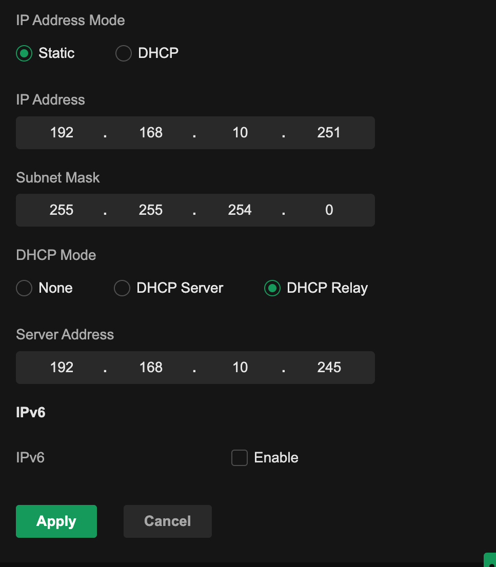
Setup the SVI on the POE switch for VLAN 10
Set IP to 192.168.10.251
Set Mask to 255.255.254.0
Set DHCP Relay to 192.168.10.245 (Secondary Router / DHCP server)
STEP 6
Set up the vlan 10 interface on the CORE switch as well (not shown here, refer to above step and diagram, IP is 192.168.10.253 in this demonstration. Set its DHCP relay to the main router IP for vlan 10 192.168.10.254)
STEP 7
Set up the Transit VLAN SVI on ALL THREE switches (refer to diagram at the top)
(here is example of the LAN switch)

STEP 8
Set Switch Static routes
The POE and LAN switch should both route 0.0.0.0/0 > 192.168.2.253 (the Core Switch)
The Core Switch should route 0.0.0.0/0 > 192.168.2.254 (the Router interface on the Transit VLAN)

STEP 9
Set up the Gateway Route
Set up the gateway static route so internet traffic is returned to the core switch transit vlan IP

Conclusion
WiFi clients of VLAN 10 now get an IP in the .11.X range
LAN clients of VLAN 10 now get an IP in the .10.X range
Both clients get a 255.255.254.0 subnet mask, so can directly communicate
All switches have SVIs in all VLANs so inter-switch routing is handled seamlessley between them without ever touching the gateway
Routing loads are split evenly across the three switches, each switch hadling routing for INCOMING traffic into it from either clients or the Main Router
You can now set reservations for each half of the VLAN on its respective DHCP server. You can also specify any IP address in the entire range , for example, you can reserve .10.100 for a raspberry Pi on WiFi. The Other DHCP server will not give this out to LAN clients as it always pings to make sure an address is free.
